Friday, January 6, 2012
Thursday, January 5, 2012
How To Remove Wood Bungs to Expose Screws

As can be seen, the bungs aren’t exactly easy to locate. Sometimes you really have to look close with good lighting to find them all. Before you try to remove any piece of wood, triple check that you have located all of the bungs. If you try to pull off a piece and a screw remains, you have a good chance of damaging the wood. Ask me how I know

- An impact driver with the correct bit (flat head for my screws)
- A drill with a 1/4″ forstner bit
- Hammer
- Cheap 1/4″ chisel
By cheap chisel, I refer to the kind you can get from Home Depot in a 5 pack for about $15. I am not referring to a fine woodworking chisel. Some woodworking tool enthusiasts see my use of chisels as an improvisational tool and nearly choke on their drink at the misuse of the tool. These people need to chill out a little bit and realize that the chisels I use are very cheap, sturdy, and can take abuse. Save the fine woodworking chisels for their purpose, but don’t be afraid to abuse the cheap ones for whatever you can come up with.

The first step is to drill out the bung in the center using the forstner bit. Use a forstner bit that is smaller than the bung size, in my case a 1/4″ bit. Apply enough pressure and drill until you reach the screw hidden beneath the bung. Do not drill too hard into the screw or you can tear up the head.


Most of the time the screw slot will be filled with glue or wood from the bung, and the chisel is required to clear the screw slot. Usually you can do this with a little effort by hand, but a tough one will require you to hammer the chisel into the slot to clear the junk.
This brings up a point about these slotted screws. Before I developed this system, I began to seriously loathe slot headed screws and cursed the boat maker for using them to hold on everything. The slots are so easy to slip out of (until I found the joy of the impact driver), and easy to strip the slot of its edge. I figured anything other than a slot headed screw would be preferred.
However, the genius of the slot headed screws is that if you strip the head, you can still use it with some working of the chisel and hammer. Insert the chisel into the slot and hammer away on it, using both sides of the chisel to create a deep enough groove for the driver bit to latch onto. If these were phillips or other type of screw heads, you would strip the head and be completely screwed (lol) and would have to resort to more difficult methods of removing the screw. The slotted screws have enough un-cut space on the head to give you room to re-bore the screw slot and give it a new edge. While some screws took a bit of effort with the chisel and hammer, re-stripping the screw, chisel and hammer, repeat….they all eventually came out. Just keep at it and it will work.

Continuing on….depending on the bung and how it was glued in, you may be able to skip the next steps and just use your chisel. Some bungs that are not solidly glued in will come out with a little bit of effort on the chisel. With the chisel inside your pilot hole, you might be able to wedge it underneath the bung and carefully pry it out. Sometimes you might even be able to break up the bung with the chisel in the pilot hole and easily remove it. However, most of my bungs were glued in and wouldn’t come apart easily so if that is your case, continue on with the next steps.
With the screw head exposed, there should be enough room to insert your driver into the screw slot and slowly, CAREFULLY, back the screw out. I always test to see if the screw will back out easily turning by hand using either the chisel or another small screwdriver. Sometimes it will back out, but most of the time it requires the impact driver and all the power behind it. As the screw backs out it will push the bung out with it and if all goes right, create a clean hole.

With clean holes, you will be able to refinish the wood or whatever need to do and insert new bungs when re-installed.

However, among the thousands of bungs I removed on Windsong, only about 5% would come out easily with this method. Most of the bungs were glued in solidly and would generally crack and crumble when the screw is trying to pull them out. Not only that, but if the screw really bites on the bung and pulls it out while solidly glued, it might crack and damage the surrounding wood as it is forced out. I ruined many a good bung hole (HA!) using this method.
When the bung cracks under this method, a mess is left behind that needs to be cleared out by the chisel. I find that using the forstner bit to make a large pilot hole for the chisel before anything else is far more efficient and safe for the wood. As mentioned previously, sometimes all you need is the forstner bit hole and chisel to remove the bung. If you need more help, at least you are left with a flush pilot hole instead of a chopped up mess. Through much trial and error, I came to appreciate the method I outlined above.
However, no method is 100% fool-proof. You will strip many screw heads, and if you do, follow the advice I gave above on slotted screws. Sometimes no method seems to work well, and you end up just chiseling away at the wood and damage the surrounding area, or you just accidentally ruin the flush hole. Fear not, as long as it isn’t serious and large damage, you can just drill out a larger bung hole later on. For example, on all of the bungs I screwed up I plan on drilling out 1/2″ holes to re-plug.
Wednesday, January 4, 2012
Heap Big Job Mate! A new cockpit floor with Beckson Hatches
The original sole looking aft at left
.
A big job replacing the cockpit sole with Beckson hatches for access. Mark Corke explains how...
When I built Mallard my gaff rigged cutter I was never quite sure how to finish off the sole of the cockpit. On the one hand the cockpit needed to be water tight but on the other hand I also needed to have access for essential maintenance to the stuffing box and primary fuel filter. The other problem was that the cockpit sole was very close to the water line so rigging up the drains so that they would be self draining also became something of a headache, on a larger boat with more free-board the sole is higher and the water can run through drains and exit the boat above the waterline. This was not possible on Mallard so in the end I connected both drains to an inch and quarter sea cock in the bottom of the boat. This worked well enough but it meant that the sea cock had to remain open even when I was not on the boat and this made me nervous not least because if the clamps let go or the sea cock failed water would flood in and the boat would sink. I thought about the problem for several years not quite sure what to do. Finally I came up with the solution that you see in the following pictures, the old sole was completely removed and a now marine plywood sole installed. Two Beckson watertight hatches were fitted to allow continued access to the area under the cockpit and the drains were routed to a self contained sump pump which keeps the cockpit dry and means that the large sea cock can be dispensed with allow me to sleep easier at night.
Of course every boat will be different and if the hatches are installed in a cored fiberglass deck then I would recommend scooping out some of the core after the cut out has been made and filling with a thicken epoxy to prevent water from migrating into the core material.
One final point and that is to carefully think through the install before you go cutting into anything; will the hatch interfere with anything above and below decks, will it weaken the boat and do I have the necessary skill set and tools to enable me to complete the installation in professional manner.
Here's how I went about it in words and pictures.
Step one was to remove the old drains, which were big, mostly because they incorporate a non return ball valve to prevent water from sloshing back up into the cockpit.
The next step was probably the most time consuming of the whole project for me, it was certainly the messiest. Using a Fein multimaster I cut out the existing sole but left the bearers in place as I would need these later to support the new sole.
Once the old sole was out of the way I was able to accurately measure for the new half inch marine plywood that would make up the new section. I then cut this out with a circular saw with a fine tooth blade but I could have used a jigsaw. To allow a little room for the epoxy and also to make sure that the ply would not get jammed in I allowed an eighth of an inch clearance all the way around.
After cutting out the ply to the correct overall dimensions the cut outs for the hatches were marked and then cut out with a jig saw. Like the overall size of the play I made the cut outs and eighth oversize to allow for a little movement.
I then bored for the new drains which was much easier to do off the boat. I used a drill press which gave a perfect hole but a hand held drill would have been almost as good had the machine not been available.
I used a brass plumbing fitting from my local home store which has a screw on one end and a barb on the other which is perfect for three quarter inch inside diameter hose. With the holes drilled I had a dry run before permanently gluing them in position.
Mixing up some epoxy thickened with colloidal silica and wood flour to a mayonnaise consistency I used mahogany dust which gives it the brown color.
I then spread a goodly amount onto the screw threads and the inside of the hole and screw the fitting down into position, notice the squeeze out which is ideal. I then left the epoxy to set overnight.
With the epoxy set I used an 80 grit disc on the random orbit sander to sand the brass fitting which was slightly proud of the plywood flush. It is important to keep the sander moving for if the brass gets too hot it will soften the epoxy and could weaken the bond.
There are two things to do before the the sole can finally be permanently glued in place; drill and countersink holes for the fixing screws and coat both sides of the sole with unthickend epoxy to seal out any moisture.
The sole is then ready to be installed and I glued it in place with epoxy thickened to the consistency of peanut butter with colloidal silica which makes a very strong bond once set.
With the epoxy still wet the sole is screwed in place. In truth the epoxy is plenty up to the task without using any screws but the screws hold the sole in place whilst the epoxy sets up and don't do any harm if left in position. I used brass screws but if they were in an area that were to be subjected to a lot of sea water than I would have used bronze.
With the sole screwed in place I used some more thickened epoxy to fill over the top of the screws and form a fillet (pronounced fill-it) in the corner to provide a smooth transition from the cockpit side to the sole. A maxed out credit card with the corner trimmed to a large radius makes the perfect tool.
When the epoxy has set after a day or two the whole sole and fillets were lightly sanded and the paint applied to match the existing surrounding paint. I have found that the best paint over epoxy seems to be the Interlux Epoxy Prime Kote which is then followed up with the colored top coats.
With the paint dry the next and final stage of the job can start. The hatches are dropped back into position and the holes for the mounting bolts made. I used an automatic center drill to create a pilot hole. When all these have been completed I removed the hatch once more and set it aside.
On the underside of the hatch in hard to read writing is stamped 'use a 12 mm diameter drill'. This is to allow the hatch to move during temperature extremes. It may be tempting to simply fix the hatch in place with some suitable wood screws but it you do there is a good chance that the plastic around the mounting holes will crack as the hatch expands and contracts at different rates to the ply substrate.
Using the pilot holes as a guide I drilled the holes to the specified 12 mm with an auger drill.
The hatch is ready to be installed but before squirting on the silicone I taped some blue painters tape all around the opening where I knew it would project under the hatch flange. With the hatch dropped back in place a razor blade is run around the perimeter tracing the outline and cutting through the tape.
The hatch is once more removed and the tape on the inside of the cut is peeled off.
Some silicone sealant is applied around the entire perimeter.
The hatch is then bolted into position with 10-24 stainless steel flat head machine screws, backed up on the underside with fender washers and nuts which are also stainless.
Then the perimeter tape is peeled up pulling any squeeze out with it leaving a nice clean and tidy job with no need of any rags or chemical solvents.
The finished job all ready for another season. A teak floor grating will be installed in due course.
A Simple Home Made Bilge Pump
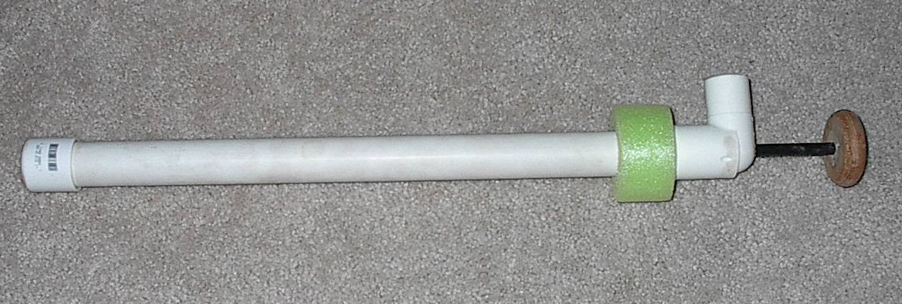 |
| Finished Pump |
Here it is. A simple home made bilge pump.
It is made of:
1" thinwall PVC about 24" long,
1" end cap,
1" street L,
24" fiberglass tent pole,
2 long screws that fit tightly in the hollow tent pole,
10-24 nut and bolt,
a piece of plastic cutting board cut to fit snugly inside the PVC tube,
some scrap inner tube rubber,
a wooden disk for a handle,
a little bit of Snoodle.
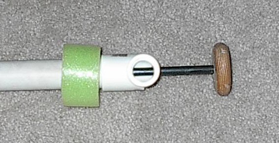 |
| Output Port |
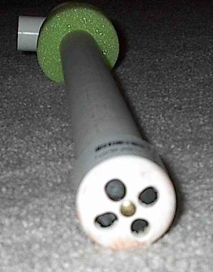 | |
| Input Port |
 | |||||
| The Plunger Valve |
I cut the plastic cutting board material to make a plug that was a snug fit inside the PVC tube. Then after drilling a center hole I drilled 4, 3/8ths inch holes around the center.
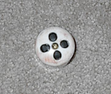 | ||
| The Valve |
Then I cut a piece of inner tube so it was just a little larger in diameter then the PVC tube, centered it on the tent pole, and screwed the holed plug on.
 |
| End Cap |
I drilled a center hole in the end cap, and 4, 3/8ths holes around it. Then I used a rat tail file to elongate those holes, being careful to leave an area outside of the elongated holes on inside for the inner tube to seal against. Then using the center hole, I bolted another piece of inner tube cut to fit snugly to the inside of the cap.

I drilled a 3/8ths inch hole through the top center of the street L inserted the tent pole through the hole, and screwed a wooden knob to the outside end.
Then I just shoved the end cap on one end and the street end on the other. NO GLUE IS USED!!!
The snoodle is just for a floatation test, I will adjust the amount of snoodle used to ensure the bilge pump floats.
It takes a few strokes to prime the pump, but once it starts pumping it works very well. I may sew a section of nylon cloth into a tube that fits snugly over the output port to aid in directing the water overboard. Credit goes to a Mr Anderson who published this on the internet. You will also find various versions of this with a Google search. Enjoy!
Tuesday, January 3, 2012
Saving Wet Electronics
OK so I am sure that I am not the only sailor that has dropped a cell phone in the water from my pocket whilst bending over to tie the boat to the dock.
Assuming that you can get the phone back, I managed it with a kids fishing net attached to a boat hook as the water was not too deep, what do you do next or is a waste of time?
If the cell phone or other electronic device was dropped in salt water you need to rinse it thoroughly under the faucet, I know this seems like the wrong thing to do but trust me you need to get rid of the salt crystals. Remove the battery if you can as this makes cleaning out the inside easier. Shake off as much of the excess water as you can then pat dry with paper towels. Finally bury the phone or other electronic device in a clean dry bowl of rice and leave over night. The rice will attract and absorb most if not all of the remaining moisture left in the device. With luck the phone or other electronic device will have survived and lived to ring another day.
Even if you manage to dry out the equipment it would be wise to get it to an approved service center asap so they can take it apart and check the inner workings.
Tip for the Removal of Pencil Marks
Here is a tip that you might not know about. If you are setting out work with a pencil and you make a mistake or other wise need to remove an errant pencil mark from a wood surface use alcohol. It takes pencil marks off in a jiffy, the alcohol evaporates almost right away and it will not damage the workpiece at all. Erasers work fine some of the time but they leave a black mark often which you still have to get rid of, sanding with a piece of abrasive paper often scratches the surface and is hard work, alcohol simply rubs the mark away.
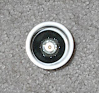
Recovering Distorted Raw Water Impeller
 |
| Reverse stress stake out |
Now, after I remove the impellor and give the blades a good inspection for deterioration, I stake it out on a piece of wood with nails and distort the offending blades back in the opposite direction. I leave this for a few weeks/months until the blades look close to "normal" again.

If the impeller came from the raw water pump about to be used. I just put in a new one to get the boat going, and place the "recovered one" into spares as it becomes "UN-distorted:"
This trick should save me some money. I hope it does for you too!
Monday, January 2, 2012
An Alternative to the Yellow Brick
Personal Locator Beacons
Accessories
Docking Stations
Voice and Data Terminals
So many choices these days. To me this looks a little better than the Yellow Brick. What do you think???
So here's the Hype........
Overview
Iridium Extreme is the toughest handset ever from the only company that offers real global, real mobile, real reliable communications. Engineered with more features and more accessories than any other satellite phone on the market, Iridium Extreme puts more innovative capability — and more ways to connect than ever before — into the hands of people everywhere.
Standardized: A highly capable handset needs a highly capable network to empower it. Iridium Extreme is built with the same reliable voice and data capability that Iridium users have come to trust, and backed by the world's only satellite network that commands real global coverage, pole to pole.
Optimized: From desert to mountain, savanna to tundra, Iridium Extreme puts more powerful capability into the hands of people, around the world. It has more features and accessories than any other satellite phone. It is the only one with real time tracking. It is the only satellite phone with GPS-enabled SOS with emergency services supported by GEOS Travel Safety Group Limited, included at no additional charge. And it can connect with Iridium AxcessPoint to create a Wi-Fi hotspot to keep in touch on your trusted devices — everywhere.
Ruggedized: No other phone in the world has more guts or grit than Iridium Extreme. It is the first phone with military-grade 810F durability. It is dust proof, shock and jet-water resistant. From emergency crews and paramedics to military personnel and government operations, Iridium Extreme is built for the world's toughest, highest usage customers to make the connections that matter under the harshest conditions, anywhere on the planet.
Sunday, January 1, 2012
Tracking Beacon and Emergency Alert
This device could be very useful for some. Thought it was worth the post to those who like this sort of solution.
Yellowbricks are tracking beacons – they work anywhere on Earth using the Iridium satellite network, and are programmed to send back a position at regular intervals. They are self-contained with their own internal batteries and antennae, are very easy to fit, and are therefore ideal for yachting, expeditions, treks and other adventures.
If you are looking to purchase a Yellowbrick, click here to find out more
WiFi onboard with an iMux
iMarine Apps gives a good account of the Brookhouse iMux. I just might get one of these for the iPad which is sure to come one day. Read on...
Brookhouse iMux
 What the heck is an iMux? Well, glad you asked. Mux is short for multiplexer and the i wirelessly connects your iPhone, iPad or iPod touch providing data from all your ships electronics and navigation hardware. This is truly a geeky item folks.
Brookhouse iMux
 What the heck is an iMux? Well, glad you asked. Mux is short for multiplexer and the i wirelessly connects your iPhone, iPad or iPod touch providing data from all your ships electronics and navigation hardware. This is truly a geeky item folks.
Brookhouse is run by a bunch of Kiwis from New Zealand. They have been around since 2002 providing solutions for integrating marine electronics on commercial and recreational yachts. A multiplexer combines many sources of NMEA 0183 data and creates a single stream of data that can be used by computers, chart plotters and other navigation devices. It takes data from any NMEA 0183 source such as, depth sounder, speed sensor, wind direction indicator, wind speed indicator, radar, weather station, GPS or fluxgate compass. I can them provide the data to any number of computers, laptops, smart phones, or tablet for use with navigation programs.
Features:
- 4 opto-isolated “NMEA Listener” (Input) ports, 3 at 4800 bps, 1 at 38400 bps for AIS.
- 1 RS232 output port for connection to a chart plotter or computer
- 1 RS232 input port
(baudrate conversion input). - 1 Output RS422 port (differential NMEA talker port) 4800bps
(baudrate conversion output) - Baudrate conversion 38400bps-4800bps.
- Indicators: red LED for power, green LED for data-transmission.
- Supply Voltage: DC 9-35 Volts.
- Reversed polarity protection.
- Physical size: 110x65x37mm (hxwxd)
- Weight: 140 grams
- Mounting: bulkhead mounting with screws.
- NMEA management and control:
- NMEA Sentence Filtering
- NMEA Sentence editing “on the fly” for NMEA protocol conversion.
- Automatic port switching.
This device is unique in that it does not require a computer to operate. So you can leave your laptop at home and wirelessly receive all your ships data on your iPad. The unit works great with the iNavx application and the Brookhouse website has alot of information on how to integrate an iMux into your ships systems and work with you iPad. iNavx is a great navigation and charting program which can be used on the iPad or iPhone.
Brookhouse has other multiplexers with USB and Bluetooth capabilities. Check out their website for the one that fits your needs. They do have a iMux-ST version which allows integration of SeaTalk data from your Raymarine instruments.
You can order your very own iMux for $299.00.
Subscribe to:
Posts (Atom)